top of page


IR Hexbug Mod
- Control a stock Hexbug with a TV remote -

Though the new Hexbug PC board (HXB27e) accommodates the Vishay TSOP34838 IR receiver module to provide advanced control functions via the PIC microcontroller, simple control of a standard Hexbug can be added by just adding an IR receiver module to the stock circuit board. The only requirement is that the TV remote IR frequency matches that of the receiver. Most TV remotes use 38 kHz as the carrier frequency. (See further information on frequencies at the end of this article.)
How the Reverse-Turn works -
The stock Hexbug has two behaviors: march straight ahead, or do a reverse turn for two seconds, then go back to marching straight ahead. The reverse turn is triggered by bumping its antenna, or a loud noise. Either of these actions triggers a timer circuit that switches the H-bridge to reverse the motor.
The collector of NPN transistor Q1 is normally high, keeping the H-bridge in the motor-forward state. When the antenna is bumped, it charges the 47uf capacitor C1, which discharges through a 6.8k resistor and the base of NPN transistor Q1 causing the collector to go low. With the collector low, the H-bridge is now driven to the motor-reverse state. It takes approximately two seconds for the capacitor to finish discharging, and then the bridge goes back to the motor-forward state.
A loud sound triggers the same circuit. The electret-microphone’s signal is amplified by two transistors to create a negative going pulse. This pulls down the base of PNP transistor Q2 (connected in parallel with the antenna switch) and charges the capacitor. As the capacitor discharges, it drives the motor in reverse as it did when the antenna was bumped.
The IR Upgrade -
Now that we know how the reverse turn is triggered, let’s examine how the IR receiver module works so it can be interfaced to the Bug’s stock circuit.
The output of the TSOP34838 IR receiver module is the collector of an NPN transistor pulled up to the supply voltage by a 30k resistor. When any IR signal is detected, the NPN transistor pulls this line to ground. If the IR signal is pulsing on and off (the control data from the TV remote), the output transistor will match the on/off pattern of the signal. This pulse/data rate is much faster than the 2 seconds of the reverse turn, and will trigger the reverse turn circuit.
We can now see that the output of the IR module and the Bug’s amplifier circuit are the same, though the pull-up resistor on Q3 is only 2.2k.
One other point to note is that there is no current limiting resistor in the base path of Q2. In the stock circuit this is not a problem because the signal conditioning limits pulse width to a very short time. I do not consider this good circuit design, but due to the low power of the whole system, the internal impedance of the small batteries and the base and saturation voltage of the transistors, the current will be limited to a safe value in this case. In the modification, we will limit Q2’s base current, and the current the IR module must sink with a 2K resistor. If we left the 2K resistor out, a wide pulse from the IR controller would consume excessive current and shorten battery life, and possibly damage the TSOP34838. (Its sink current is rated as 3ma Max.)
Assembly -
The diagram shows where to connect the IR module, which should be connected through a 2K resistor.This module was chosen because it has the lowest operating voltage I could find- 2.5 volts. Some that I have tested worked at 2.1 volts, but, at lower than operating voltages, it started to trigger erratically with out any IR.

First, remove the batteries. The outer shell is held on with eight pins that press fit into sockets in the body.
Remove the bug’s shell by wedging an X-Acto blade or other narrow edge tool between the body and the shell mounting posts.

Twisting the blade slightly will start the separation. Once the joint has opened up a little, use the blade as a lever to pop it free. Carefully loosen all seven of the outer press fit pins, and the eighth center one will also come free.
Locate the Ground terminal area on the PC board (Red Circle in earlier figure), scrape it clean and tin it to prepare it for soldering the module in place.
Next, we need to prepare the IR receiver module. Since the part is static sensitive (Yes, I fried one while prototyping), take it out of its static protection bag by holding all three leads simultaneously between the fingers of one hand, then wrap a fine bare wire around the leads. By picking up the part by all three leads and then connecting them together with the wire, no unequal voltage can build up on any one pin to damage the device. This will make it easier to form the leads without concern for damaging the part. The fine wire is removed after installation.
Follow the diagram for general bending guidelines and adjust the leads as you go to fit it the PC board contact points. Take care to hold the leads close to the body of the IR module when bending them. ( Holding just the body to bend the leads may damage the part according to some manufacturers. A little extra care now can prevent problems later. Remember Murphy’s Law...) Leaving the ground lead long will provide a useful handle when soldering the part onto the circuit board. It can be trimmed off later.
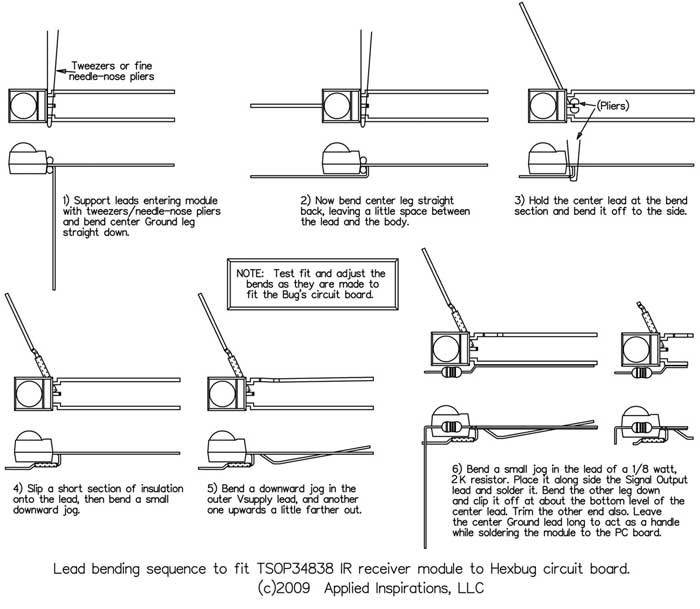

Note the safety wire wrapped around the leads to prevent static damage during all the bending and fitting. One part of the wire weaves over the center lead and under the other two to assure contact. The wire is removed after soldering.
After bending, fitting and trimming, locate the points indicted in the picture, and carefully solder the TSOP34838 to the stock circuit board. Gently adjust its position to center it just behind the mounting screw and square and level to the board. REMEBER to remove the static-safety wire from the IR module before re-installing the batteries!!

(NOTE: Yes, the pictures show a 1K resistor. Further analysis showed this to be a little too close to the part’s specified current limits for comfort, so the value was increased to 2K after the prototype was built.)

Final Modifications -
A hole must be drilled to accommodate the IR module if the shell is going to be replaced. Temporarily place the shell on the body, and site where the IR module’s dome touches it. Remove the shell and drill a tiny hole (~1/16") there. Check the fit again, and adjust the hole so it’s centered over the module. Use this guide-hole and enlarge it until it’s just a bit larger than the module’s dome. Finally, file or cut a square section toward the front of the shell.

NOTE: With this modification, the Bug will do a two second reverse turn when it is first powered up because the TSOP34838’s output starts in the low state, pulling the timing capacitor low. Test the Bug, and if all has gone well, replace the shell by lining up the pins with the sockets in the body and firmly pressing the two together.
Your new bug is now ready to answer your commands!All right...it’s just one command,... and it’s only reverse turn. Well, it’s a start. Have fun with it, and then consider building one with a full brain transplant.


Additional IR Remote Control Notes:
A very good tutorial on IR Remote Control Theory with detailed information on the different control formats can be found at: www.sbprojects.com/knowledge/ir/ir.htm
The Vishay TSOP348xx IR receiver module series is compatible with other frequencies. The last 2 digits specify the frequency.
Standard IR remote control frequencies:
Addition information on IR receivers can be found at Vishay’s website:
www.vishay.com/docs/49860/0811wd_d.pdf -Choosing a receiver
www.vishay.com/docs/80067/appoverv.pdf -General
bottom of page