1-Cell White LED Driver
Light White LEDs from a single Alkaline cell
White LEDs normaly require about 3.5 to 5.5 volts to opperate, so how do you use
a single 1.5 volt alkaline cell to light one?.
That's it - 2 Transistors, 1 resistor, and a simple transformer
White LEDs require anywhere from 2.95v to 4.5v to operate, so small LED flashlights typically use three alkaline cells to light them. If they are AAA cells, then the internal impedance of the battery (read that: equivalent built-in internal resistor of the cell’s chemistry) limits the current. Bigger cells (C’s and D’s) require some sort of control or ballast resistor. AAs are right on the edge, and though the LED shines brightly, it dies early. Typical rated current for a small LED is about 20-30ma, and up to an amp for larger high power ones.
There are specialized ICs that will accurately control the current, and others that will also boost the supply voltage so a single cell can light a high power LED. Their draw backs (a side from the fact that they are a specialized IC) are typically their tiny size, specially selected additional components, and critical PCB layouts.
The Circuit:
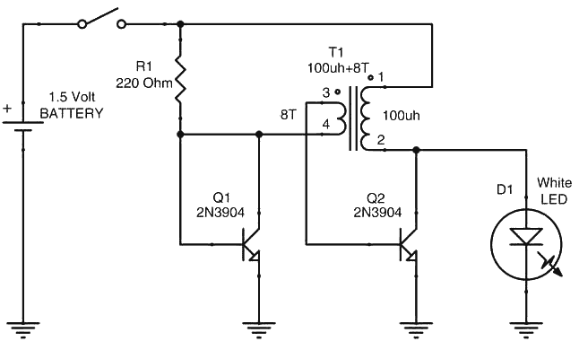
I have seen many discrete LED drivers, many using a 555 timer, but there is one design in my collection that is exceptional. Sad to say, it’s not my design. It’s one of those “Of course! I should have thought of that!” It was created by Jim Grant and was featured in EDN’s Design Ideas for February 15, 2007 issue. The circuit uses only four components (not including the LED and battery) -
2 common NPN transistors
1 resistor
1 transformer
Ok, I can hear the groans already ( even over the net), but there’s good news! I just got a great rate on my insur. . . No, no, that’s not it. The “transformer” is very, very simple- a small, very stock, open form (they are also the cheapest), 100uh inductor with eight turns of wire added to it.
Several Different coils, the form is not critcal
To improve efficiency, the series resistance of the inductor should be as low as practical. Three good inexpensive candidates are:
Make the Transformer:
To modify the inductor, first, remove the shrink tubing that covers the coil. (Some inductors will be open and won’t require this step.) Be careful not to nick the wire underneath. Angling the X-acto knife helps.
Take note of the direction the wire is wound, and identify a ‘start of winding lead’. We’ll call it pin 1. This is the one you will connect to the battery.
Next, take a short length of fine wire (anything from #36 to #26), and wind 8 turns around the existing winding in the same direction.
We’ll call the start of this winding pin 3, and the end pin 4. Pin 4 will be connected to the resistor / transistor-base connection, pin 1 to the battery, pin 2 to the LED and the collector of Q2, and finally pin 3 to the base of Q2. Once the new windings are in place, re-wrap the tape over them. (Or use new tape if you prefer.)
Now, wire up the circuit using a proto-board, perf-board, or just free-form solder the parts together. Check that things are wired correctly, and connect to a battery. If the circuit doesn’t work, and you’ve check to see that everything is wired as in the schematic, it is possible that the polarity of the transformer’s leads got mixed up, so try reversing 3 & 4.
Operation:
When power is first applied, current flows through R1 and the 8 added turns of wire into Q2’s base, turning it on. This allows current to start flowing through the main windings of the inductor. As the current through the inductor increases, Q2 eventually goes into saturation (It’s passing the maximum amount of current it can pass at that voltage), and the magnetic field of the inductor stops increasing. (Increasing magnetic fields induce a positive current, and a decreasing magnetic field induces a negative current flow.) If the current in the inductor is not changing, then the magnetic field is not changing, and there is no current induced in the 8 turn secondary. This reduces the current flowing through Q2’s base, which in turn starts to reduce the collector current, and therefore the current through the inductor and the 8 turns.
Things now reverse. With the inductor’s magnetic field collapsing, a reverse current is induced in the 8 turn secondary, and Q2 is completely turned off. Now all that magnetic energy in the inductor must go someplace, so as the magnetic field continues to collapses, the voltage on the LED’s anode increases until current flows and the LED lights.
Eventually, the inductor’s magnetic field reaches zero, having dumped its energy through the LED, and the reverse current in the 8 turn secondary also ends, allowing R1 to pass current to Q1’s base starting the cycle all over again.
So, what is Q1’s role in all this? Obviously, it’s not a switching element, with its base and collector tied together. Q1 provides the bias point and temperature compensation for Q2. Being the same type of transistor, its base voltage drop will closely match that of Q2. This means that a very small voltage across the 8 turn secondary will have a large effect on Q2. Since R1 sets the current flow through Q1, it sets the bias voltage for Q2, and therefore Q2’s saturation point and the maximum current through the inductor. Making R1 larger will reduce the LED’s brightness, and decreasing R1 will increase it.
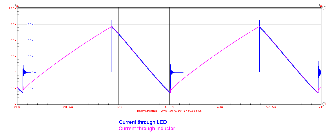
Note that the current through the LED is not continuous, but is a series of pulses at around 87kHz.
Waveforms:
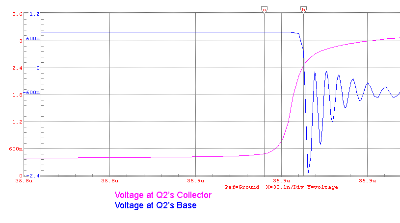
This simulated scope trace shows the transition point- The collector voltage starts to increase causing the base voltage to decrease. The transition takes only about 15ns.
This trace shows the current through the inductor, and its transition from flowing through Q2’s collector (visible red) that stores energy in the inductor during one cycle, and the inductor dumping that energy into the LED during the next cycle.


