

Hexbug Hack
HexBug Hack
1 Possibilities
2 What's Inside
3 Controller Design
4 Assembly
5 Controller Software
6 Testing, Programming --and Final Assembly
7 Downloads
8 Upgrades
Give your Hexbug a Real Brain!
Chapter 4 - Assembly -
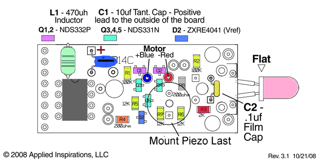
Although the new controller can be built on a pad-per-hole prototyping board, using a printed circuit board will be much more convenient. A double-sided, plated through hole and solder masked board can be obtained from Applied Inspirations, LLC.

The last components to get soldered to the PC board should be the antennae (due to there fragility and to prevent the insulator between the post and the spring from being distorted during surface mount soldering.) The first components to be mounted on the PC board are the surface mount parts. (Make sure the surface mount parts are soldered before the piezo-buzzer; it installs over the H-bridge.) Only the resistors and MOSFETs are surface mount components for several reasons:
1) Surface mount ceramic capacitors should NOT be soldered by hand, one contact at a time. They tend to crack or short internally and fail. Or worse- they may be slightly damaged and fail intermittently. Intermittent problems are the most difficult to debug.
2) The PIC chip is socketed so that different chip versions can be used, it can be replaced if damaged, and so it can be programmed externally, and then plugged into the board. If external programming is used, the connector pins and jumper can then be eliminated, and a simple switch used to turn the bug on and off.
3) An axial leaded filter choke is less expensive and smaller than its equivalent surface mount package.
4) Resistors and SOT-23 MOSFETs have enough flex in their packaging to prevent damage when hand soldered.
NEW HXB27e Parts List:
( The Assembly sequence is basicly the same )
NOTE: Most of these parts can also be obtained from Digikey and other suppliers.Resistors, capacitors, the zener, and LEDs can be easily substituted for, however,Do Not substitute Parts in BOLD BLUE without careful evaluation for equivalence.

NOTE: These are the original, HXB14c, Exploded Assembly Sequence and Parts List.They will be updated in the future and archived in a reference section that will be maintained for all early project versions.


(NOTE : The MOSFETs used here, NDS331N and NDS332P, are special Low Gate Voltage parts. If other MOSFETs are substituted, make sure their turn-on gate voltage is low enough. )
The surface mount devices (SMDs) can be hand soldered, one at a time, with fine solder and a fine tipped, low power soldering iron- preferably temperature controlled. (Use anti-static precautions, and install the resistors first to help protect the MOSFETs’ gates.) I did my first surface mount projects this way, until I discovered what sadly seems to be:
The ‘best kept secret’ of surface-mount prototype assembly-
I met Dave Jacks, president and founder of Zephytronics at the ’06 NEPCON show. (I almost left early and would have missed him.) He was demonstrating Zephyrtronics’ line of surface mount repair and prototyping equipment. My eye’s got wider as he deftly demonstrated soldering and unsoldering finely pitched, 44 pin chips from a PC board as quickly as one of those “never needs sharpening” knife demos, where they cut a tomatoes into fifty, paper thin slices in the blink of an eye. Only, this was not snake oil!
The commercial way of assembling surface mount components is to screen print solder past onto the PC board, place all the components with a high speed automated placement machine, and then run the board through a controlled temperature-cycle oven.
Though the solder paste and components can be placed by hand, and boards have been soldered in toaster ovens, the biggest problem is the solder past itself- it must be shipped cold, and if not refrigerated, the solder and flux will separate, and harden up.
If you are willing to live with this, Digikey has it- a 100gr syringe is about $57, and must be shipped overnight express; more $$$.
A Better Way
There is however, a better way- Zephytronics has pioneered a solder paste that does not need to be refrigerated. They have developed a solder paste that is stable, on the bench for six months, and much longer if refrigerated. I’m almost out of my first tube I bought two years ago, and it’s still good. When not being used, I keep it in one of those tiny, dorm-room type refrigerators. A 10cc syringe is about $15, and they have no minimums.
Their website has a great deal of very good ‘how-to’ as well as technical information about surface mount soldering (http://www.zeph.com/pap1.html). They sell some excellent equipment, though it’s a bit pricey for hobbyists.
For occasional / limited surface mount soldering, a good, digitally controlled heat-gun will work. The best deal I’ve found is the one offered by Ace Hardware, and it’s under $35 if ordered over the web. Additionally, a thermocouple temperature probe should be used to monitor the air and board temperature. Some good digital multimeters include them.
There will be more information on surface mount soldering on this website laterThe surface mount soldering section is still under construction.
NEW HXB27e Parts Placment:

(Click Image for Detailed .PDF Diagram)
NOTE: This is the original, HXB14c, Parts Layout.It will be archived in a reference section that will be maintained for all early project versions.
The basics of this assembly method are:
1) Spot apply solder paste to all the surface-mount pads.
2) Place the components, and align them with the pads. (In most cases, if the pad geometry is correct, the surface tension of the liquid solder will pull the parts into alignment, but they need to be close.)
3) Place the board in a semi-enclosed area (sheet metal or plasterboard are two good possibilities) to help direct the hot air from the heat-gun to the board’s underside. Place the tip of the temperature probe so it’s pressed against the top of the board.
4) Over about a minute’s time, slowly ramp up the temperature to 300°F. Let the board ‘soak’ at this temperature for about a minute. The board and components can safely be left at this temperature for extended periods of time. The flux component of the solder paste will cause it to first flow, and then will dry out.
5) Raise the air temperature to about 430°F quickly and carefully watch for the solder to flow. As soon as the solder has flowed on all the pins, quickly reduce the air temperature, and let it cool back to room temperature with just air.
After the surface mount parts have been soldered, install the capacitors, piezo-buzzer, inductor, and the 8-pin header (or jumpers) and 8-pin socket. The leads of the LED should be insulated and bent to place it between the antennae. It should also be inserted from the BOTTOM of the board if the transparent bug shell will be replaced. Finally, install and solder the antennae to the BOTTOM side of the board. Note that there are right and left antennae!
To be able to program the PIC chip in circuit, and test the Bug’s performance, a programming cable will be needed. This can be wired up using an 8-pin female header for the Bug side, and a 5-pin male header for the PICkit-2 side. (Other Microchip and third party programmers will work also, but may have different pin-outs and/or external power requirements.)

Before the new board is installed on the Bug chassis, it should be tested- It’s a bit of a pain to unsolder it from the battery terminal wires once it’s installed. And before it can be tested, we need a control program.
Just for reference, as the board can not be tested without software:
The final assembly is done by first soldering the motor leads to the controller (but NOT the battery connections), applying power and verifying system functionality, particularly that the motor is running the right way. (If it does get wired in backwards, the solution would be to reverse the software definition of forward and reverse. But we don’t make those kinds of mistakes, now do we?) The screw holding the chassis halves together is removed, and the board is placed on the chassis, lining up the battery pins with the PC holes. Reinstall the screw and solder the battery pins.
1]The micro-robotic Hexbug is the result of collaboration between Ignition (Plano, TX; www.ignition.com), an industrial design and development firm, and Innovation First Inc. (Greenville, TX; www.innovationfirst.com), a product engineering company. RadioShack is the exclusive North American retailer of the Hexbug. Bandai, the leading toy manufacturer in Japan, also recently signed a deal for global distribution rights, with plans for other products to follow. “We had a rough idea for this product, but Ignition brought it to life,” says Joel Carter, VP of marketing at Innovation First. “They transformed our concept into a viable market-ready product and helped us to create an entirely new product category.”