

Hexbug Hack
HexBug Hack
1 Possibilities
2 What's Inside
3 Controller Design
4 Assembly
5 Controller Software
6 Testing, Programming --and Final Assembly
7 Downloads
8 Upgrades
Give your Hexbug a Real Brain!
Chapter 6 - Testing, Programming & Final Assembly -

SETUP-
(NOTE: This section assumes that you have some knowledge and experience using MPLAB and using the PICkit-2/1 to program chips.)
‘SMOKE-TEST’-
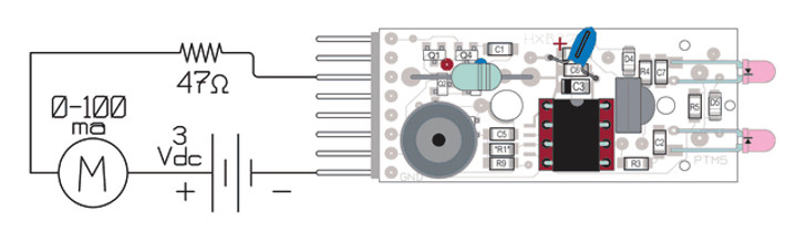
First power-up connections- The ‘Smoke-Test’
Connect a 0-100 milliamp meter in series with a 3 volt DC supply and connect the negative side to the header’s ground pin.
Apply power to the VinL pin through a 47Ω resistor. (This will limit the current to a max. of about 64ma., preventing damage even if something is in backwards.) The current should be less than 1ma.
[If it is more than this, quickly disconnect power and look for the cause. The PIC chip should have ground on pin 8, and plus supply is on pin 1. Check that the tantalum capacitor’s polarity is correct. Look for shorts.]
Remove power.
PROGRAMMING-
Having started MPLAB and assembled the code, setup the Bug for programming. Connect the PICkit-2 to your development PC with the USB cable, then select and initialize the programmer from the toolbar in MPLAB. (You can use the “ PICkit-1 Classic” application to program the chip using the .HEX file.) Next, connect the PICkit-2 to the Hexbug with the programming cable. (Note polarity: The White triangle, White wire, White stripe on header socket, and White stripe on Hexbug PC board. The white stripe will be on the Bug’s ‘right’ side.) Plug the programming cable into the Bug, then plug the cable into the PICkit-2. Click the ‘Re-establish connection’ button in MPLAB.
Download the program. When it has completed, the program will start running, and the sound tests will run.
(The LED will not light because that pin is being used by the PICkit-2.)
FULL TEST-

Motor connected, full test setup
Remove the programming Cable, and solder the motor leads to the board, but Do Not Solder the Battery terminals.
Jumper the ISCPCLK and GP-1 pins together, and then VinL to Vmot.
Reconnect the external DC supply as before- negative to ground, and the positive lead to the milliamp meter.
Connect power to the VinL pin. The current should still be less than 2-3ma (but may go to 75ma when the motor is running), and the LED should blink.
[ If the current is more that this, there could be a short, the N & P MOSFETs may be installed in the wrong places or damaged, or there could be a short. Find the problem before continuing. ]
Bump the antennae and the test routine runs:
Final Assembly -
If everything tests out OK, carefully remover the screw holding the chassis halves together, place the board on the chassis, and line up the battery pins with the PC holes. This can be just a bit fussy, and may require tweezers and a bit of wiggling. (DON’T let the case come apart while doing this!) Reinstall the screw and solder the battery pins.

Tested PCB mounted on Bug chassis
SHELL-
Because of the height of the circuitry, the post in the middle of the Bug’s shell will need to be extended. The simplest way is to slip a length of small heat-shrink tubing onto it, and just shrink the end. Another way would be to cut off the post, and glue an extension piece of plastic between the shell and post.

POWER-JUMPER BLOCK-
The final part to make is the power-jumper block. This is just a short, 6 section piece of a snap-apart header-socket strip. The six sockets are wired as shown to jumper the ISCPCLK line to the piezo buzzer, and connect the battery to both the control circuitry and motor when the block is placed on the six left-side pins. When this block is placed over the six right-side pins, the battery is disconnected- the Bug is off.
Using header pins and header sockets like this solves the problem of needing a special switch to turn power on and off and swap the connections for programming pins. The MCLR, ICSPDAT, & ICSPCLK lines must not be loaded by the Bug’s circuitry, or the PICkit-2 will not function.

The current Rev.27e board can use one of several 8 pin, flash PIC chips: 12F510,635,629,675,683. The PIC12F683 has the largest program space of the group. This board is set up so that the chips can be programmed externally, or in the Bug using Microchip’s PICkit-1, PICkit-2, (or other Base-Line-Flash programmers) and a simple 5 wire adapter cable.
In addition to the PIC socket, the HXB27e board contains:

Don’t Panic- Programming PIC microcomputers is easier than you think-
If you are not familiar with the PIC assembly language and would like to get started, there is a good, free online tutorial, “PIC Assembly Language for the Complete Beginner” by Michael A. Covington at:http://www.covingtoninnovations.com/noppp/picassem2004.pdf
Another good resource is the "Beginners checklist for PIC Microcontrollers" at:http://www.piclist.com/techref/piclist/begin.htm
Microchip offers a really great development kit for the flash series of microcomputers- the PICkit-2. Available through microchipDirect, Digikey or Mouser:DV164120 - Development kit: Programmer, Prototyping board, MPLAB software, Assembler &, Debugger - $49.99
1]The micro-robotic Hexbug is the result of collaboration between Ignition (Plano, TX; www.ignition.com), an industrial design and development firm, and Innovation First Inc. (Greenville, TX; www.innovationfirst.com), a product engineering company. RadioShack is the exclusive North American retailer of the Hexbug. Bandai, the leading toy manufacturer in Japan, also recently signed a deal for global distribution rights, with plans for other products to follow. “We had a rough idea for this product, but Ignition brought it to life,” says Joel Carter, VP of marketing at Innovation First. “They transformed our concept into a viable market-ready product and helped us to create an entirely new product category.”